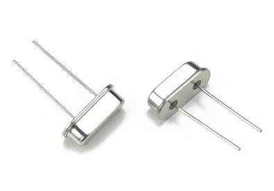
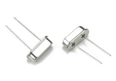
1. Introduction of crystal oscillator
Each single-chip microcomputer system has a crystal oscillator. The whole process is called a crystal oscillator. The crystal oscillator plays a very important role in the single-chip microcomputer system. It combines the internal circuit of the single-chip microcomputer to generate the necessary clock frequency of the single-chip microcomputer. The execution of all the instructions of the single-chip microcomputer is established. On this basis, the higher the clock frequency provided by the crystal oscillator, the faster the operating speed of the microcontroller.
The crystal oscillator uses a crystal that can convert electrical and mechanical energy into each other to work in a resonant state to provide stable and precise single-frequency oscillation. Under normal working conditions, the absolute accuracy of ordinary crystal oscillator frequencies can reach 50 parts per million. Advanced accuracy is higher. Some crystal oscillators can also adjust the frequency within a certain range by an external voltage, which is called a voltage-controlled oscillator (VCO).
Second, the role of crystal oscillator
The function of the crystal oscillator is to provide the basic clock signal for the system. Usually a system shares a crystal oscillator to facilitate the synchronization of all parts. Some communication systems use different crystal oscillators for the fundamental frequency and radio frequency, and they are synchronized by adjusting the frequency electronically.
The crystal oscillator is usually used in conjunction with a phase-locked loop circuit to provide the clock frequency required by the system. If different subsystems require clock signals of different frequencies, they can be provided by different phase-locked loops connected to the same crystal oscillator.
The crystal oscillator generally adopts the capacitor three-terminal (colpitts) AC equivalent oscillation circuit as shown in Figure 1a; the actual crystal oscillator AC equivalent circuit is shown in Figure 1b, where Cv is used to adjust the oscillation frequency, and a varactor diode is generally used with different This is also the mechanism of voltage control. The equivalent circuit of the crystal is replaced by the crystal as shown in Figure 1c. Among them Co, C1, L1, RR are the equivalent circuit of the crystal.
Analyzing the entire oscillation tank circuit, it can be seen that using Cv to change the frequency is limited: the entire tank circuit capacitance C=Cbe, Cce, and Cv, which determines the oscillation frequency, are connected in series and connected in parallel with Co and then in series with C1. It can be seen that the smaller the C1, the larger the Co, and the smaller the effect on the capacitance of the entire tank circuit when Cv changes. Therefore, the frequency range that can be "voltage controlled" is also smaller. In fact, since C1 is very small (on the order of 1E-15), Co cannot be ignored (on the order of 1E-12, a few PF). Therefore, when the Cv becomes larger, the effect of reducing the frequency of the tank circuit becomes less and less, and when the Cv becomes smaller, the effect of increasing the frequency of the tank circuit becomes greater and greater. On the one hand, this causes the nonlinearity of the voltage control characteristics. The larger the voltage control range, the more severe the nonlinearity; on the other hand, the feedback voltage (the voltage on the Cbe) assigned to the oscillation becomes smaller and smaller, which finally leads to the suspension of the oscillation. The higher the frequency of overtones, the smaller the equivalent capacitance C1; therefore, the smaller the frequency range.
The clock sources of microcontrollers can be divided into two categories: clock sources based on mechanical resonant devices, such as crystal oscillators and ceramic resonant tank circuits; RC (resistance, capacitance) oscillators. One is the Pierce oscillator configuration, which is suitable for crystal oscillators and ceramic resonant tank circuits. The other is a simple discrete RC oscillator.
Use a multimeter to measure whether the crystal oscillator is working: measure whether the voltage of the two pins is half of the chip's working voltage, for example, whether the working voltage is about 2.5V if the working voltage is +5V of the 51 single-chip microcomputer. In addition, if you touch the other pin of the crystal with tweezers, the voltage changes significantly, which proves to be a vibration.


